Figure 1. The KH1 Series adjustable ON DELAY module connection diagram. View is from the flat side with the catalog numbers. Time delay is variable and dependent on the resistance value of Rt. Rt @ 0 Ohm = minimum delay, Rt @ 1M Ohm = maximum delay. Module LOAD at Pin 2 is a relay coil. Rt and relay are customer-supplied components and are connected externally to the module.
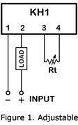
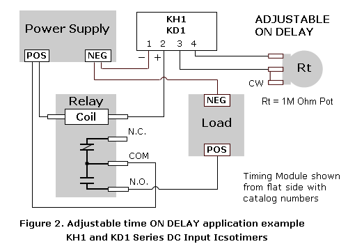
Figure 2. Illustrates a basic time delay module application with an adjustable timing range. In this example, the DC timing module is connected to the power supply, relay coil and potentiometer.
The timing period begins when the power supply is turned on. The relay activates at the end of the time delay and the load is energized through the relay contacts. The load remains energized until the power supply is turned off. Turning off the power supply resets the module and deactivates the relay. A switch can be connected between Pin 2 and the coil for resetting the module without turning off the power supply.
The timing period begins when the power supply is turned on. The relay activates at the end of the time delay and the load is energized through the relay contacts. The load remains energized until the power supply is turned off. Turning off the power supply resets the module and deactivates the relay. A switch can be connected between Pin 2 and the coil for resetting the module without turning off the power supply.
Application Wiring for "Fixed" DC Time Delay Module
Figure 3. KH1 Series fixed time ON DELAY external connection diagram. View is from the flat side with the catalog numbers. Time delay is factory preset to one specific time, 5 seconds for example. Module LOAD at Pin 2 is a relay coil.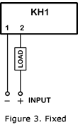
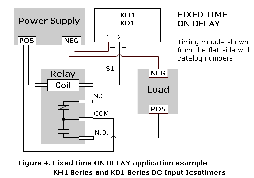
Figure 4. Outlines a basic application with a "fixed" time delay. The description and operation of the circuit is the same as the above for the "adjustable" DC time delay module only the delay is fixed instead of variable.
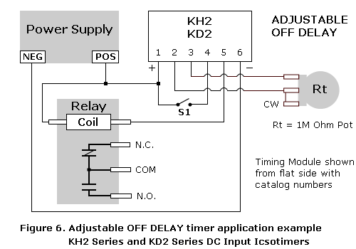
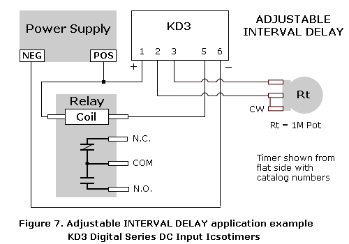
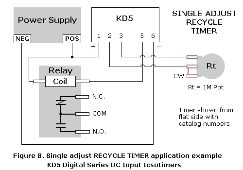
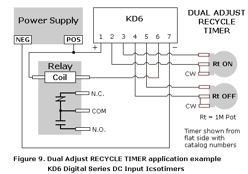
Figures 6, 7, 8 and 9 show more wiring diagrams and sample applications for adjustable time delay modules. Both AC and DC Series timers are available with either adjustable or factory preset timing ranges.

Be careful when working with live circuits!
Verify wiring is correct before applying power to circuit. Use standard safety practices to avoid personal harm and/or damage to equipment and property.
Notes:
1. KH1 and KD1 Series modules share the same lead pattern and are wired identically. KH2 and KD2 Series modules share the same lead pattern and are wired identically. When viewing the timer from the flat side with the catalog numbers and the wires pointing downward, Pin 1 is on the far left.
1. KH1 and KD1 Series modules share the same lead pattern and are wired identically. KH2 and KD2 Series modules share the same lead pattern and are wired identically. When viewing the timer from the flat side with the catalog numbers and the wires pointing downward, Pin 1 is on the far left.
2. Heatsink leads when soldering close to the module.
3. KD6 Recycle Series: Timing resistor for ON time connects to pins 2 and 3. Resistor for OFF time connects to pins 4 and 5.
4. KD5 and KD6 Recycle Series: OFF period starts first at power-up.
5. Time vs. Resistance: Rt = 0 Ohm = Minimum Time, Rt = 1M Ohm = Maximum Time. A potentiometer or fixed resistor can be used for Rt on adjustable units.
6. For KH1 Series, select a relay that draws between 10 mA Minimum and 100 mA Maximum at rated coil voltage. KH2 Series: 10 mA Minimum and 500 mA Maximum. KD Digital Series: 20 mA Minimum and 500 mA Maximum. Icoil = Vdc / Rcoil
7. Output from a DC power supply may remain at a significant level after it is turned off due to filter capacitors in the power supply maintaining a charged state. This residual voltage may prevent a time delay module from resetting.
8. External wiring connections on AC and DC input modules are identical. The drawings above can be used as reference for wiring AC input units.
9. For long-range delay modules, use the equations below to find the approximate value of the timing resistor "Rt" for your application.
Equation 1: Cycle the timer with Rt = 1M Ohm and record the maximum delay time in seconds as "Tmax". Plug the values of "Tmax" and "Tdesired" into the equation.

Equation 2: Cycle the timer with a test resistor (Rtest) of arbitrary value such as 470K ohms and record the delay time in seconds as "Ttest". Plug the values of "Tdesired", "Rtest" and "Ttest" into the equation.

For links to more information on adjustable and fixed time delay modules, visit our Sitemap page.

