Interval Timer
Typical application of a KD3 Digital Series Interval Timer is to control an externally connected relay. When voltage is applied, the output is energized and the digital timer begins a countdown interval. Upon completion of the countdown, the output is de-energized. On adjustable units, an externally connected resistor determines the duration of the time interval. The timer resets when input voltage is removed.
Timing range options are either Adjustable or Fixed from .05 seconds to 10 hours. AC input voltage options are 12, 24, 120 and 240 VAC. DC voltage options are 12, 24, 48 and 110 VDC. Output current range is 20 ma. to 500 ma.
• Timing from .05 second to 10 hour
• Digital Countdown Delay Circuit
• Fixed or Adjustable Timing Range
• Miniature PC Board
• Thick Conformal Coating
• Printed Circuit Mounting
Table 1. Part Number Selection
Action:
(3) Interval Timer
Fixed or Adjustable
Ranges:
Standard Timing
(1) 0.1 to 10 second
(4) 1 to 60 second
(2) 10 to 600 second
(5) 1 to 60 minute
Nonstandard Timing
(3) 10 to 600 minute
(0) *Special Time
*customer defined
Input Voltages:
Standard Voltage
(2) 24 VAC
(1) 120 VAC
(8) 12 VDC
(4) 24 VDC
Nonstandard Voltage
(7) 12 VAC
(5) 240 VAC
(6) 48 VDC
(3) 110 VDC
KD3xx Icsotimer Order Code
Example: KD 3 1 4
KD = Digital Countdown Series
(3) = Action = INTERVAL TIMER
(1) = Range = .1 to 10 Seconds
(4) = Input Voltage = 24 VDC
*Options: Fixed and Special Time ranges from .05 seconds to 10 hours.
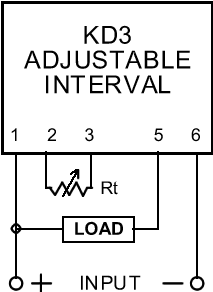
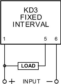
Note. Load and Rt in wiring diagrams are customer supplied items.

Adjustable Time
Shown from the flat side
Rt @ 1M Ohm = max.time
Rt @ 0 Ohm = min. time

Fixed Time
Shown from the flat side
Delay interval is fixed
Example: 5 seconds
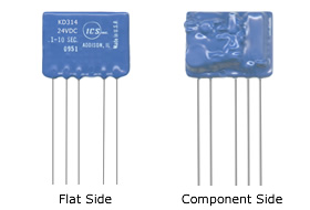
Wiring Diagrams: *When viewing the timer module from the "flat side" with the catalog numbers and the leads facing downward, Pin 1 is on the far left.
Table 2. Specification and Dimensions
Input Current:
Idle = 5 ma.
Outut Current:
Maximum = 500 ma.
Minimum: (AC Only) = 20 ma.
Output Voltage:
(Input voltage less on-state voltage drop)
On-state voltage drop:
(AC) = 2.0 VRMS
(DC) = 1.5 VDC
Operating Parameters:
Repeat Accuracy:
Fixed Conditions = ± .5%, ±1 cycle for AC units, Overall variation = ± 3%
Input Voltage Range:
± 10% @ 50 or 60 Hz for AC units, ± 10% @ 20% max. pp. ripple for DC units
Temperature Range:
-10º to 70º C operating
-20º to 85º C storage
Reset Time:
50 ms.
Typical Size (less leads):
1.4"L x 1.1"W x .5" Thick
Termination:
22 AWG solid tinned copper leads 1.75" Long


